Even if you perform manufacture and reconstruction
based on this technical
know-how of web and a trouble occurs, our
company does not have any responsibility.
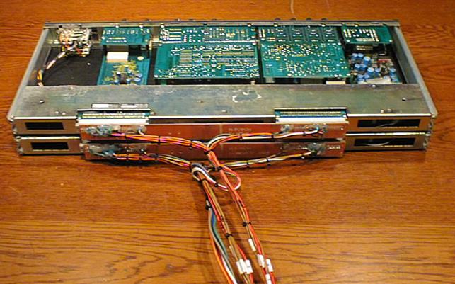
inclusion NEVE83010 module
Though it was regrettable, since it has forgotten
to take a photograph from the front, a complete
view photograph is only this
There is a request as although it is the
module purchased at Yahoo! auction,
and internal repair was allowed to do a term
by conditioning with
which is not performed for three months again.
I think if it becomes reference in case you
assemble.
An order of the visitor
Phantom is required although what form is sufficient
as a power supply.
I want to use a microphone, and Lines in
and EQ and a compressor.
A case is not needed if the cable is pulled
out.
Although I looked at the photograph which
I had sent, since there was no difference
not much with V1, I received work.
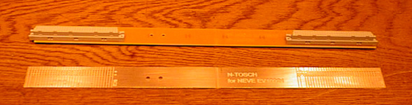
A mistake is made in putting, since the number
of connectors with the same form is two
.I made a PCB board like a lowerphotograph
Although it was a difficult star ground when calling it NEVE, it ignored this time.
power supply part
Since there was a power supply of TASCAM
M-600, 24V circuit will be added to this.
There was no pin in the connector of HIROSE,
two lines for temperature detection were
diverted to 24V.
Phontam SW was attached next to the power
supply switch.-15V for logic are made from
-16V for the diode.

The power supply transformer and stabilization
power supply part for 24V which were added
![]()
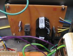
Truly, since it is an old power supply, solder
has floated in some places.
It is the condition seen by especially the
large-sized part relation.
The leg of an electrolysis capacitor has
floated with the photograph under

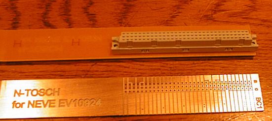
A use connector is 96P connector of DIN.
A left-hand side thing is what was used this
time, and is an object for PCB boards.
The right pulls out a line by the wrapping
type and is tube processing.
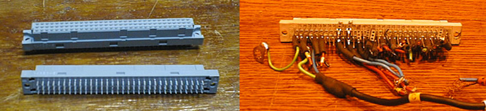
The type under this is made to the maintenance
of the module of V1.
It is the type stuck by pressure and inserted
in a pin.
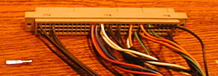
Wiring material is thin, it has hardened
by resin.。

Since it will be troubled if wiring material
is not mostly clear anymore,
a cable is numbered and thecard has also
been attached further.

Although the wiring diagram was able to be
borrowed by the courtesy of a friend about
wiring, though it was regrettable, there
was no wiring diagram of 10924 portions,
and although it may not be completeness,
it saw later on personally.
Even if you perform manufacture and reconstruction
based on this technical
know-how of web and a trouble occurs, our
company does not have any responsibility
| c | BC2 | a | It is related with connection. | ||
| 1 | |||||
| 2 | It is red hot white cold altogether . | ||||
| 3 | |||||
| 4 | FADER RETURN GND | 1 Mic in | |||
| Blue | +48V | 5 | +48V | 2 Line in | |
| 6 | 3 insert send | ||||
| Gray | -25V | 7 | -25V | 4 insert return | |
| 8 | 5 Fader send return | ||||
| Orange | +25V | 9 | +25V | FEDA connects white to a tap. | |
| Line GND | 10 | Line GND | 6 Out White left Red is the right. | ||
| LINE in Hi | 11 | LINE in Lo | Red2 | ||
| 12 | |||||
| INSERT RETURN Hi | 13 | INSERT RETURN Lo | red4 | Mic and Line in. If insertion send and | |
| GND | 14 | GND | receivesis connected, sound will come out. | ||
| INSERT SEND Hi | 15 | INSERT SEND Lo | brwon3 | ||
| Green | GND | 16 | GND | Note | |
| LOGIC 0V | 17 | LOGIC 0V | When you use ch on/off, please use | ||
| White | -16V | 18 | -16V | it in the state of on of soloSW. | |
| LOGIC -15V | 19 | LOGIC -15V | Via a diode from -16V | ||
| Red | +16V | 20 | +16V | ||
| 21 | |||||
| 22 | |||||
| 23 | |||||
| 24 | |||||
| 25 | |||||
| 26 | |||||
| 27 | |||||
| 28 | |||||
| 29 | |||||
| Mic in GND | 30 | Mic in GND | 茶1 | ||
| Mic in Hi | 31 | Mic in Lo | |||
| 32 | |||||
| c | BC1 | a | |||
| 1 | |||||
| GND | 2 | ||||
| GND | 3 | L out | |||
| 4 | R out | ||||
| 5 | |||||
| 6 | |||||
| 7 | |||||
| 8 | |||||
| 9 | |||||
| 10 | HA out | ↓ | |||
| 11 | Lim | ↑ | |||
| 12 | EQ out | ↓ | |||
| 13 | FADER in | ↑ | |||
| 14 | |||||
| 15 | |||||
| Green | 16 | GND | |||
| 17 | |||||
| Red | 18 | +16V | |||
| Withe | 19 | -16V | |||
| 20 | |||||
| 21 | |||||
| FADER send GND | 22 | FADER send | Brwon5(red) | ||
| Brwon5(withe) | FADER return | 23 | when not using FADER | ||
| 24 | connects 23c with 22a | ||||
| 25 | |||||
| 1 out | 26 | 2 out | |||
| 4 out | 27 | ||||
| 3 out | 28 | 2 out(mix) | |||
| 1 out(mix) | 29 | ||||
| 30 | |||||
| 31 | |||||
| Red6(red_right) | Right OUT | 32 | Left OUT | Red6(white_left) |
Thank you for seeing to the last. If there
is strange English, please let me know.
coming soon F.A.Q and The inside of 83010
Module